Choosing the right Electric Actuator begins with understanding the application, not browsing product catalogs. A valve in a dusty water plant faces different demands than a damper inside a clean manufacturing room. Load, stroke length, speed, duty cycle, and mounting space all influence the correct choice. Voltage and control signals matter too. A mismatch can cause overheating, slow movement, or premature failure.
Real-world selection also requires attention to the surrounding system. Engineers should check temperature, moisture, vibration, corrosion, and maintenance access before approving a model. An actuator may meet its rated torque yet perform poorly when friction increases or the valve sits unused for months. That detail is easy to miss. It should not be.
Reliable decisions come from verified data sheets, installation instructions, test records, and recognized technical requirements. Compare starting torque with operating torque, then include a sensible safety margin recommended by the manufacturer. Avoid choosing the largest unit automatically. Oversizing can increase cost, energy use, and mechanical stress. Undersizing is worse.
A practical review should also examine feedback options, manual override features, fail-safe behavior, enclosure protection, and spare-part availability. Ask how the actuator will be inspected after installation. Ask what happens during power loss.
No selection guide is perfect. Site conditions change. Specifications can be incomplete. That is why experienced engineers confirm critical details with suppliers and test the actuator under realistic loads whenever possible. The best Electric Actuator is not simply powerful or affordable. It is the one that delivers controlled, repeatable movement throughout the system’s expected service life.
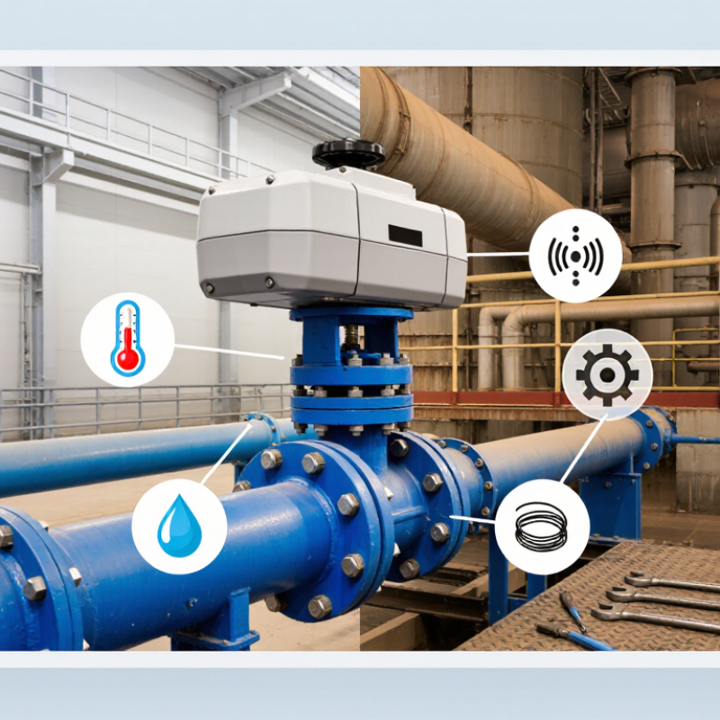
How to Choose the Right Electric Actuator?
Understanding Electric Actuator Types and Operating Principles
Electric actuators convert motor rotation into controlled mechanical movement. A rotary actuator turns a valve or damper through a defined angle. A linear actuator pushes or pulls using a lead screw, ball screw, or belt mechanism. Multi-turn actuators provide repeated rotation for rising-stem valves and positioning equipment. Quarter-turn models suit butterfly and ball valves, where accurate angular travel matters.
Inside, an electric motor produces torque through electromagnetic force. A gearbox reduces speed and increases output force. The transmission then moves the load. Encoders, limit switches, or potentiometers report position to the controller. This feedback helps prevent overtravel and supports repeatable positioning. In commissioning work, I check actual stroke and torque under load, not only catalog values. Measure twice. A valve may need extra breakaway torque after storage or temperature changes.
Choose the actuator by load, travel speed, duty cycle, control signal, and operating environment. A fast actuator is not always better; excessive speed can create water hammer or mechanical shock. Check enclosure protection, ambient temperature, manual override needs, and power-loss behavior. Spring-return designs can move to a safer position without continuous power, while non-spring units may require a backup supply. I have seen selections fail because mounting alignment was treated as a minor detail. It is not. Even a small offset can increase friction, noise, and wear. Examine the interface dimensions and cable entry before installation.
| Electric Actuator Type | Operating Principle | Typical Motion and Output | Best-Suited Applications | Main Advantages | Important Limitations | Key Selection Considerations |
|---|---|---|---|---|---|---|
| Rotary Actuator | An electric motor rotates a shaft directly or through gears. The actuator converts electrical energy into controlled angular movement. | Quarter-turn, multi-turn, or continuous rotation. Output is specified by torque, commonly in N·m. | Butterfly valves, ball valves, plug valves, dampers, indexing mechanisms, and positioning systems. | Compact design, precise position control, adjustable speed, and compatibility with automatic control systems. | Gear wear may occur under high loads. Continuous operation can cause heat buildup if the duty cycle is exceeded. | Check required torque, rotation angle, travel time, duty cycle, output shaft dimensions, manual override requirements, and environmental protection rating. |
| Linear Actuator | A motor drives a lead screw, ball screw, belt, or rack-and-pinion mechanism to produce straight-line movement. | Linear extension or retraction. Output is specified by force in N, stroke length in mm, and speed in mm/s. | Lifting equipment, adjustable workstations, dampers, gates, slides, automation machinery, and material-handling systems. | Direct linear motion, accurate positioning, easy stroke control, and clean operation without hydraulic fluid. | Screw mechanisms can be sensitive to contamination. Side loads, shock loads, and excessive unsupported stroke can reduce service life. | Evaluate load force, stroke length, speed, mounting orientation, side-load protection, backlash, holding capability, and required positioning accuracy. |
| Electric Valve Actuator | A motor and transmission operate a valve. Limit switches, torque switches, or electronic sensors stop movement at defined end positions. | Quarter-turn or multi-turn movement. Output is selected according to valve torque or thrust requirements. | Water treatment, HVAC, process piping, irrigation, power facilities, and industrial fluid-control systems. | Reliable remote operation, repeatable valve positioning, feedback options, and integration with PLC or building-control systems. | Incorrect sizing can prevent valve closure or cause damage. Some designs require protection from condensation and corrosive atmospheres. | Match the actuator to valve type, breakaway torque, running torque, shutoff torque, thrust, travel time, fail-position needs, enclosure rating, and control signal. |
| Servo Actuator | A motor operates in a closed-loop system using an encoder or resolver to compare actual position with the commanded position and correct errors. | Highly controlled rotary or linear motion. Output is described by torque or force, speed, acceleration, and position accuracy. | Robotics, CNC equipment, packaging, pick-and-place systems, synchronized motion, and precision assembly. | High accuracy, rapid response, excellent repeatability, programmable motion profiles, and dynamic load control. | Higher system cost and greater commissioning complexity. Feedback cables, tuning, and electromagnetic compatibility require attention. | Define accuracy, repeatability, peak and continuous torque, inertia ratio, acceleration, feedback type, controller compatibility, and thermal performance. |
| Stepper Motor Actuator | The motor advances in discrete electrical steps. A controller energizes the phases in sequence to create incremental angular movement. | Incremental rotary motion, often converted to linear motion with a lead screw or belt. Torque decreases as speed increases. | Printers, laboratory instruments, light-duty indexing, dosing equipment, and applications with moderate speed and load demands. | Simple control, good low-speed torque, predictable incremental movement, and no feedback required for basic open-loop operation. | May lose steps during overload or rapid acceleration. Resonance, vibration, and heat generation can affect performance. | Check holding torque, running torque at the target speed, acceleration profile, load inertia, microstepping needs, and whether position feedback is necessary. |
| Solenoid Actuator | An energized coil creates a magnetic field that moves a ferromagnetic plunger, usually against a spring or mechanical load. | Short-stroke linear movement, typically for on/off operation rather than long-distance positioning. | Small valves, locks, latches, relays, dispensing mechanisms, and rapid switching functions. | Very fast response, simple construction, compact size, and relatively low initial cost. | Limited stroke and force, possible coil heating, high inrush current, and limited suitability for continuous proportional positioning. | Specify voltage, AC or DC supply, required force at the actual stroke, response time, duty cycle, return-spring action, and ambient temperature. |
| Electromechanical Cylinder | A motor drives a screw inside a cylinder-style housing. The screw converts rotary motion into controlled linear thrust. | Linear thrust with defined stroke, speed, and position. Commonly used as an alternative to pneumatic or hydraulic cylinders. | Pressing, clamping, lifting, forming, material handling, and repetitive industrial automation. | High repeatability, programmable force and position, clean operation, and efficient energy use when properly sized. | Initial cost can be higher than basic pneumatic equipment. Screw, seal, and bearing life depend on load, speed, lubrication, and duty cycle. | Calculate continuous and peak force, stroke, speed, duty cycle, load direction, mounting, backlash, braking or self-locking needs, and safety margins. |
| Integrated Smart Actuator | The actuator combines a motor, drive electronics, sensors, and communication functions in one assembly for local or networked control. | Rotary or linear motion with digital commands, status feedback, diagnostics, and configurable operating parameters. | Distributed automation, smart factories, HVAC systems, process equipment, and installations requiring remote diagnostics. | Reduced external wiring, built-in monitoring, easier data collection, configurable control, and simplified system integration. | Software and network compatibility must be verified. Electronics may require thermal management and protection against electrical transients. | Confirm communication protocol, supply voltage, cybersecurity requirements, I/O functions, diagnostic features, firmware support, and network installation conditions. |
| Explosion-Protected Electric Actuator | The actuator uses a specially designed enclosure and certified construction to limit the risk of ignition in hazardous areas. | Rotary or linear motion, selected according to the driven equipment and hazardous-area classification. | Oil and gas facilities, chemical processing, paint operations, grain handling, and other classified hazardous locations. | Designed for controlled use in hazardous environments when installed according to the applicable certification and site requirements. | Higher cost, increased weight, stricter installation rules, and limitations imposed by the applicable hazardous-area certification. | Verify hazardous-area classification, gas or dust group, temperature class, certification scheme, enclosure rating, cable entries, grounding, and maintenance procedures. |
| Fail-Safe Electric Actuator | An energy-storage device, such as a spring or backup power system, moves the actuator to a predetermined safe position when power or control signal is lost. | Usually quarter-turn or linear travel with defined fail-open, fail-closed, or fail-in-place behavior. | Safety-related valves, fire protection systems, ventilation, combustion control, and critical process isolation. | Provides a defined response during power failure or emergency shutdown conditions. | Energy storage reduces available output in some operating conditions. The fail action, reset method, and testing requirements add complexity. | Define the required safe position, fail time, emergency torque or thrust, backup energy capacity, reset method, proof-test interval, and safety integrity requirements. |
Measure the real moving load, not only the catalog estimate. Separate weight, friction, and acceleration forces. Do not guess.
Use a practical margin for uncertain loads and starting resistance. Excessive oversizing wastes energy and may reduce control quality. More power is not always better.
Specify travel speed in millimeters per second. Check acceleration, deceleration, total stroke, and cycle timing. Long strokes may need side-load guidance.
An actuator running continuously needs greater thermal capacity than one operating twice hourly. Record operating frequency and rest periods. Heat matters.
Define position accuracy, repeatability, and allowable backlash. Choose end-stop switching, analog positioning, or feedback communication based on the machine’s needs.
Check temperature, moisture, dust, chemical exposure, and available clearance. Match enclosure protection to the site. Higher protection can complicate heat management.
Verify required torque, travel, voltage, mounting dimensions, signal type, feedback accuracy, and fail-safe behavior. Also check cable routes and manual override access.
Include energy, calibration, spare parts, commissioning, and downtime. Build a five-year estimate using real duty cycles. It will be imperfect, but useful.
Record actual load, temperature, noise, response time, and cycle duration. These details can reveal problems before alarms appear. Leave room for adjustment.
Choosing the right Electric Actuator begins with understanding the available types and how each operating principle suits a specific application. Start by defining the required load capacity, operating speed, stroke length, movement frequency, and control method. These requirements help narrow the options and prevent performance issues caused by under-sizing or unnecessary capacity. It is also important to evaluate the working environment, including moisture, dust, temperature, chemicals, and potential mechanical impact, so the actuator’s materials and protection level can provide reliable service.
A complete comparison should consider power consumption, positioning precision, response speed, maintenance demands, safety functions, and noise levels. Before making a final decision, verify electrical and mechanical compatibility with the existing system, available installation space, mounting arrangements, wiring, and control interfaces. Reviewing expected service life, replacement needs, energy use, and maintenance expenses will provide a clearer view of long-term costs. A well-matched Electric Actuator can improve efficiency, reliability, and operational control while supporting safe and consistent equipment performance.

 YWOO Motor